
Collaborators
Project Brief
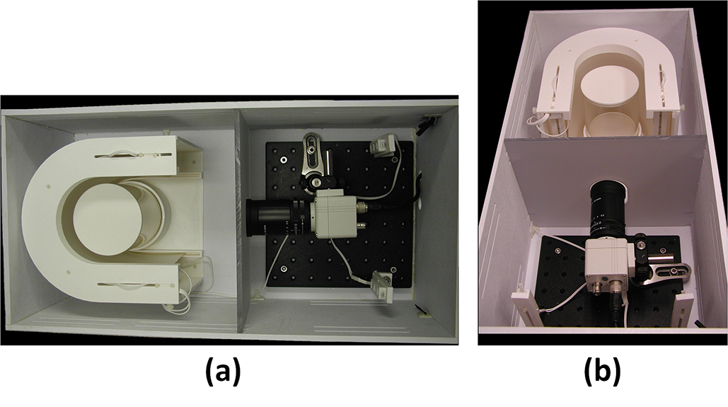
In this collaboration, EPR imaging technology is demonstrated to be a novel physiological imaging modality useful in obtaining maps of tissue oxygenation quantitatively and non-invasively with high spatial and temporal resolution. In vivo EPR imaging has been successfully implemented in small animal experiments, specifically in mouse models of human cancer to obtain information (e.g., dynamics of tumor physiology, hypoxia) critical for treatment selection (e.g., chemotherapy, anti-angiogenic drug therapy, and radiotherapy) and response monitoring. The capabilities of EPR imaging have been found to be very useful in screening anti-cancer agents, as well as understanding their mechanisms. The NIH development team, NCI Radiation Biology Branch and CIT SPIS, has designed and implemented several EPR imaging systems capable of in vivo imaging, which is often combined via co-registration with anatomic images from MRI.
The imaging systems and methodologies (e.g., microscopic histopathology for microvessel analysis) are utilized by many NIH scientists. Prior techniques, which provided such information, are either invasive or not quantitative, and there is no equivalent commercially available EPR imaging system. In contrast to MRI, EPR imaging requires lower radio-frequency (RF) power levels, faster data acquisition rates, and very sensitive detectors. SPIS engineering and prototyping expertise has been critical to addressing these hardware and software design requirements.
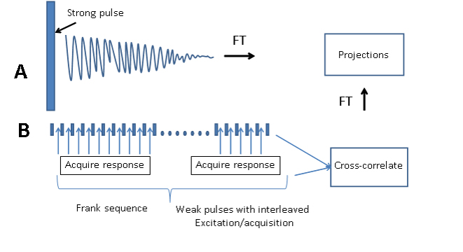
More recently, the team is evaluating integration of error-correcting codes (i.e. Hadamard, Frank, and Chu sequences), often used in telecommunication systems operating within noisy environments, with the EPR pulse sequences in an effort to reduce transmit power levels. Instead of a single high-power RF transmit pulse, hundreds of lower power pulses are generated, and a single acquisition sample is obtained between pulses. These low power pulses are modulated using an error-correcting code, and the samples are correlated with the same code to extract the free induction decay signal (FID).
The team is also working on an EPR method called Rapidscan. Until recently, EPR systems were either continuous wave (CW) or pulsed. Rapidscan EPR is a newer modality that is distinct from the more established methods.
- CW EPR – constant RF signal, constant gradient fields, varying B0 field
- Pulsed EPR – pulsed RF signal, constant gradient fields, constant B0 field
- Rapidscan EPR – constant RF signal, varying gradient fields, varying B0 field
Rapidscan EPR has some of the best attributes of the other two modalities. It offers the sensitivity of CW EPR and the faster data acquisition rates of pulsed EPR. Since the RF signal is constant, data acquisition is not hampered by dead time and coil resonant ringing. The gradient and B0 fields oscillate sinusoidally making them simple to generate. Overall, the hardware requirements for Rapidscan EPR are easier to achieve.
Block diagram of the RF subsystems within the custom pulsed EPR imaging system. The transmit box and receive box are custom-built in-house using commercially available RF components. The RF transmitter section outputs the signals through the diplexer to the EPR sample coil. The receive signals from the coil (i.e., free induction decay signals) pass through the diplexer to the RF receiver section for pre-processing before input into the data acquisition hardware.
- Towards reduction of SAR in scaling up in vivo pulsed EPR imaging to larger objects
- A new strategy for fast radiofrequency CW EPR imaging: Direct detection with rapid scan and rotating gradients
- Integration of digital signal processing technologies with pulsed electron paramagnetic resonance imaging
- Direct detection and time-locked subsampling applied to pulsed electron paramagnetic resonance imaging
- Stochastic excitation and Hadamard correlation spectroscopy with bandwidth extension in RF FT-EPR
- High-Speed Data Acquisition System and Receiver Configurations for Time-Domain Radiofrequency Electron Paramagnetic Resonance Spectroscopy and Imaging
- High Speed Digitizer/Averager Data Acquisition System for Fourier Transform Electron Paramagnetic Resonance Spectroscopy
- Radiofreqency FT-EPR Spectroscopy and Imaging
Awards
2016 CIT Director’s Merit Award